The skull melting technique is fairly specialized and is not widely used due to the rather unusual equipment required. However, it is a very powerful method in solid state synthesis.
The RF generator
One needs a radio frequency (RF) generator capable of generating frequencies in either the 200-400 KHz or 2-4 MHz range with a power of 20 to 50 KW. To put that in perspective, this apparatus delivers the power of a typical AM radio station into an area that is perhaps 30
cc in volume. This can generate temperatures sufficiently high to melt or vaporize almost any material. The power supply from a skull melter located at Purdue University is shown below:
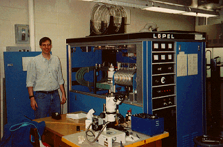
To give you a better idea of the power requirements, the main circuit breaker for the generator pictured above is shown below. Working with such high currents and voltages is safe if you know what you're doing and are careful to use only one hand when tinkering with the generator (so your body doesn't complete any circuits).
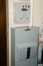
The RF coil
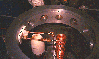
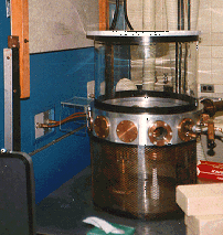
A radio frequency (RF) coil is attached to this generator. The coil itself is simply standard copper tubing which is attached to the output side of the generator with a standard fitting. Cooling water flows through the coil at a high rate to minimize any heat buildup. In the picture below, you can see the copper tubing passing through an insulating Teflon block into a reaction chamber and then forming a relatively narrow and tall coil (coils are typically wider and 4-8 turns in height). This reaction chamber is more or less a bell jar which adds a margin of safety and contains debris. The bell jar also permits one to run syntheses under a variety of different atmospheres.
When the bell jar is assembled, it looks something like this.
The sample container
The other major component of a skull melter is sketched below. A water cooled copper block with water-cooled copper fingers is placed inside the RF coil (but not touching it). The fingers are closely spaced so that the RF field can penetrate to the sample, but the powder can not flow out. In the sketch below, the RF coils are viewed from the side and cut away for clarity. These copper containers come in various sizes, with the largest ones being able to contain 1-2 kilograms of material!
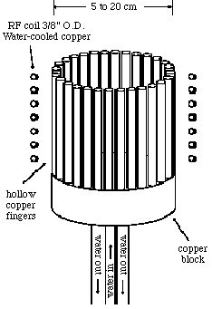
Inductive heating
RF heating is inductive, not radiative. Therefore, it is important that the material to be melted is a good electrical and thermal conductor. Many insulating materials such as oxides, carbides and nitrides do not couple to the RF frequency. However, graphite is an excellent RF susceptor. To melt an insulating oxide, a graphite ring or disk is placed in the sample. The RF field heats the graphite which in turn radiatively heats the oxide. When the oxide gets hot enough, it starts to couple to the RF field on its own. If the reaction is run under air, the graphite burns away and thus does not contaminate the sample.
The skull in action
The
skull of the skull melting technique refers to what happens when materials melt inside this setup. The copper cooling quickly removes heat from the melt, and a thin crust (or skull) of solid is formed around the outside of the melt. In this sense, the material supplies its own container, thereby providing materials with low degrees of contamination.
The copper container can be slowly lowered out of RF field during a run to provide slow cooling. Materials can also be added to the melt during the run by using a hopper feeding system. Using these techniques, large single crystals of materials such as magnetite (Fe3O4) and thoria (ThO2, m.p. 3,300 degrees C) can be grown with high purity.
Pictures can't do justice to the brilliant white light produced by a skull melter being run at 3,300 degrees C. In fact, you can't even look at it without special goggles.
Further Reading
Some skull melting web sites and books of interest are:


 The Glassware Gallery


![]()